MIL-DTL-18375H
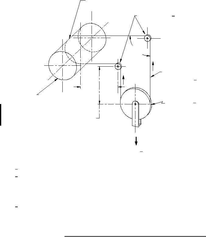
Clamp wire rope
to the drum
Test sheaves 3/3/ (see figure 2)
Test sheaves (see fig. 2)
90°
T2
Wire rope speciman
T1
under tension 1/
13.5 in. min.
Drum 16 in. dia. oscillating
rate 120 reversals per
Idler Sleeve 3/
min. and equipped
11.5 in. dia. min.
with a counter
13.5 in. min.
Force 2/
NOTES:
1/ Tension load per table II T1 = T2 = w/2
2/ Force necessary to develop the applicable tension load = w = w1 + w2 + w3, where
w1 = weight of idler sheaves
w2 = weight of hanger
w3 = weight added to hanger to make the total weight "w" equal to twice the applicable tension load
3/ All sheaves shall be supported on suitable ball or roller bearing, or on shaft extensions supported on suitable
ball or roller bearings.
4/ The dimensions of the test sheaves are test parameters only and are by no means intended as design criteria.
FIGURE 1. Diagram of endurance testing machine and conditions of the test.
14
For Parts Inquires submit RFQ to Parts Hangar, Inc.
© Copyright 2015 Integrated Publishing, Inc.
A Service Disabled Veteran Owned Small Business