MIL-DTL-18375H
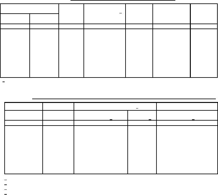
TABLE I. Wire rope construction and physical properties.
Construction
MBS before
Approximate
Diameter of wire rope
Tolerance
Allowable increase of
endurance testing
weight per
on diameter
diameter at cut end 1/
100 ft.
(plus only)
Nominal
Minimum
(reference)
in.
in.
in.
in.
lbs.
lbs.
1/16
0.062
0.010
0.009
7x7
360
0.75
3/32
0.093
0.012
0.010
7x7
700
1.60
1/8
0.125
0.014
0.011
7 x 19
1,300
2.90
5/32
0.156
0.016
0.017
7 x 19
2,000
4.50
3/16
0.187
0.018
0.019
7 x 19
2,900
6.50
7/32
0.218
0.018
0.020
7 x 19
3,800
8.60
1/4
0.250
0.018
0.021
7 x 19
4,900
11.00
9/32
0.281
0.020
0.023
7 x 19
6,100
13.90
5/16
0.312
0.022
0.024
7 x 19
7,600
17.30
3/8
0.375
0.026
0.027
7 x 19
11,000
24.30
1/ The allowable increase in diameter shall be applied to the actual diameter of the wire rope being tested.
TABLE II. Wire rope endurance test parameters and breaking strength after endurance testing.
Endurance test parameters 1/
Number of
MBS after endurance
Nominal diameter
Construction
Minimum tension load
reversals 3/
testing 4/
of wire rope
(-0, + 10%) 2/
in.
lbs.
lbs.
1/16
7x7
5.0
70,000
216
3/32
7x7
9.0
70,000
420
1/8
7 x 19
18.0
70,000
780
5/32
7 x 19
24.0
130,000
1,200
3/16
7 x 19
37.0
130,000
1,740
7/32
7 x 19
50.0
130,000
2,280
1/4
7 x 19
64.0
130,000
2,940
9/32
7 x 19
78.0
130,000
3,660
5/16
7 x 19
90.0
130,000
4,560
3/8
7 x 19
120.0
130,000
6,600
1/
The tension loads and number of reversals are test parameters only and are by no means intended as design criteria.
Tension load is equal to one-half the weight (w) as shown in figure 1.
2/
3/
2 reversals = 1 cycle. 13 1/2 inches of travel in one direction and return.
Each value is equal to 60 percent of the original MBS of the wire rope as shown in table I.
4/
12
For Parts Inquires submit RFQ to Parts Hangar, Inc.
© Copyright 2015 Integrated Publishing, Inc.
A Service Disabled Veteran Owned Small Business